Chapter 6
So far, we’ve controlled the outside world using digital output.
Now we flip the direction.
Instead of Arduino sending signals, we’ll make it listen.
This chapter answers a simple but important question:
🔘 What Is a Digital Input?
A digital input pin can read only two states:
HIGH → voltage present
LOW → no voltage
Just like digital output — but now the direction is reversed.
Instead of Arduino controlling voltage, external components control the pin’s voltage, and Arduino reads it.
🧠 The Button as an Input Device
At its core, a button:
either connects a pin to voltage
or disconnects it
No magic. No data. Just electrical connections.
🔌 The Basic Button Circuit (Concept First)
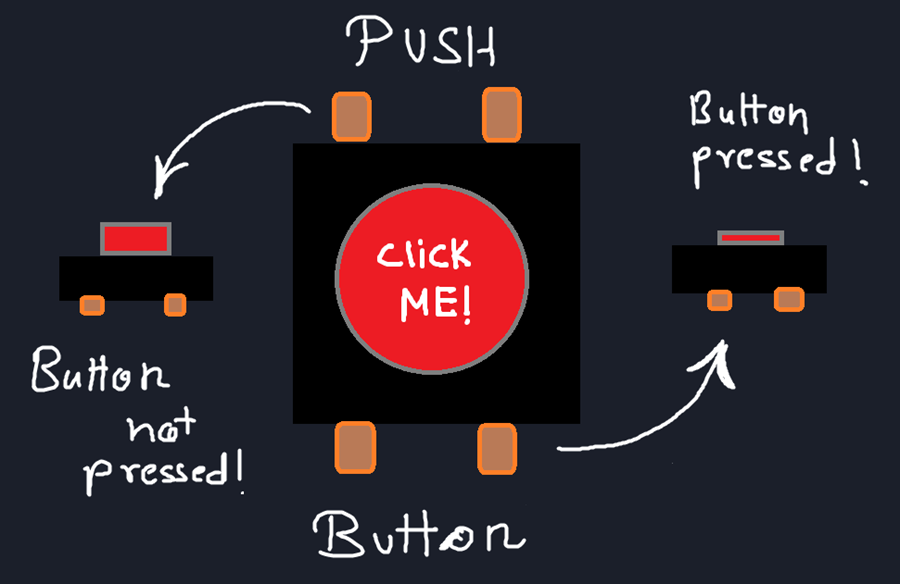
Imagine this logic:
Button not pressed → pin reads LOW
Button pressed → pin reads HIGH
That’s all we want.
But here’s the catch…
⚠️ The Floating Pin Problem
A floating pin:
can randomly read HIGH or LOW
picks up electrical noise
causes unpredictable behavior
This is one of the most confusing beginner issues — and it’s not a code bug.
🧲 Pull-Down Resistor (Classic Solution)
To avoid floating, we force the pin into a known state.
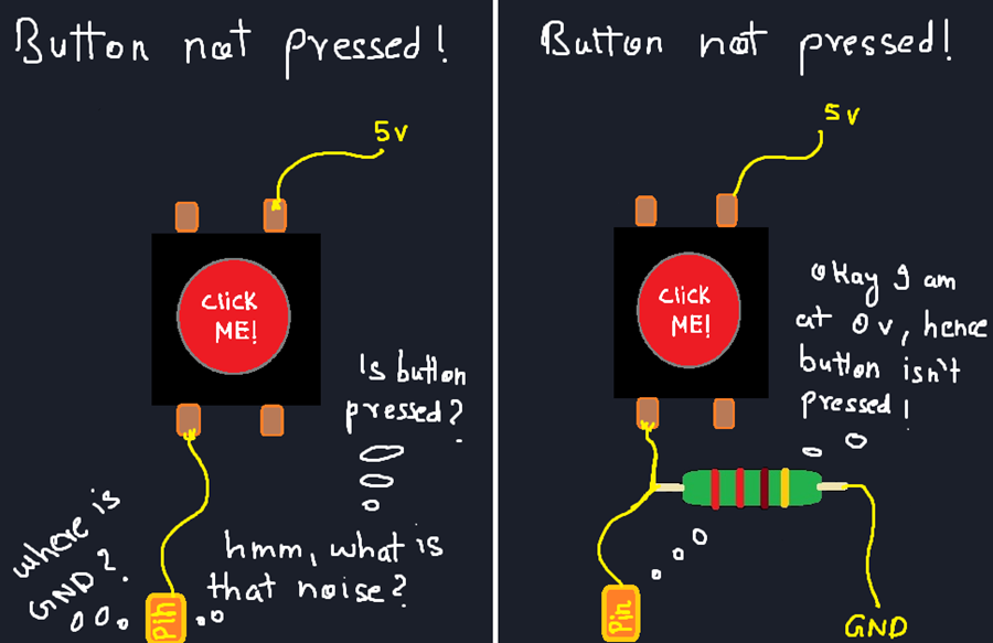
With a pull-down resistor:
the pin is connected to GND through a resistor
default state = LOW
when button is pressed, pin connects to 5V
This guarantees clean readings.
🧠 Arduino’s Shortcut: Internal Pull-Up
Arduino gives us an easier method.
Instead of using an external pull-down resistor, we can use an internal pull-up resistor.
pinMode(2, INPUT_PULLUP);
This does two things:
sets the pin as input
connects it internally to 5V through a resistor
Now:
button not pressed → HIGH
button pressed → LOW
🔄 Why Inverted Logic Is OK
People often panic when they see this.
But inverted logic is actually:
stable
noise-resistant
widely used in real systems
All because this circuitry is provided by Arduino Internally!
You just have to think clearly:
- LOW means pressed
- HIGH means released
Once you accept this, life becomes easier. :)
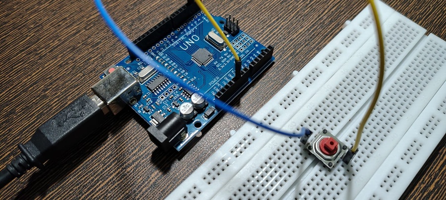
🔌 Wiring Time
Okay, bring out your hardware and start building!
Using an External Pull-Down Resistor
We’ll first show you the beginner-friendly and intuitive way to do this, using an external resistor so you can see what’s happening electrically.
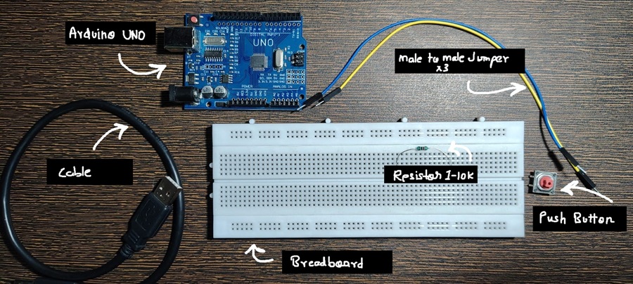
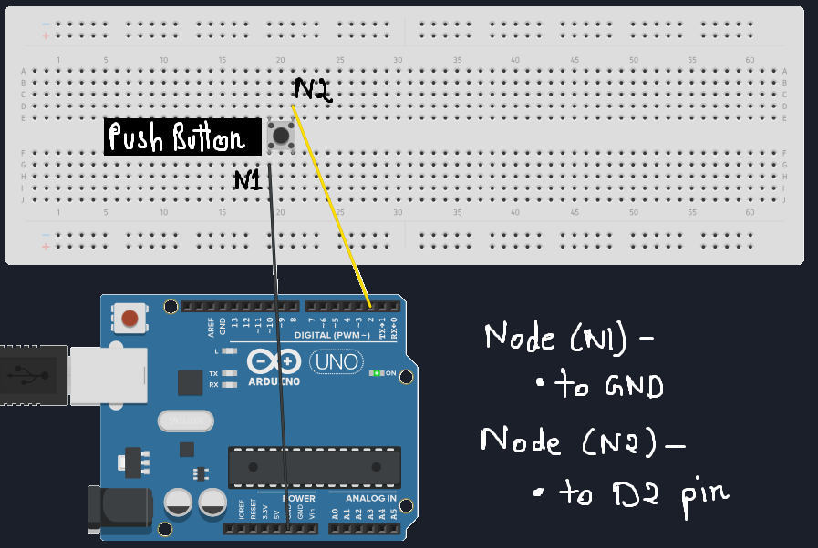
Arduino Pin 2 → Button → Resistor → GND
Connect the components exactly in this order. (Any large resistor would work!)
If you’re not familiar with how switches work internally, you can refer to this article: Swtiches.
A simple schematic is also shown in the image below to help you visualize the connections.
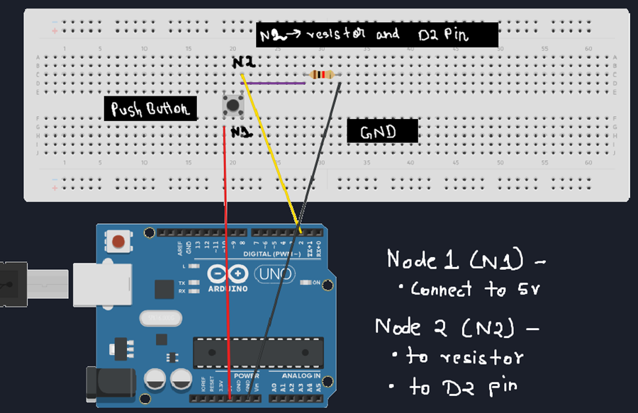
In this configuration:
When the button is not pressed, the resistor pulls the pin to GND, so Arduino reads LOW
When the button is pressed, the pin connects to 5V, and Arduino reads HIGH
This resistor ensures the pin is never floating, which is extremely important for reliable input reading.
Once everything is connected properly, plug in your Arduino and upload the code below:
const int buttonPin = 2;   // Button connected to pin 2

void setup() {
  pinMode(buttonPin, INPUT);   // Set pin 2 as input
  Serial.begin(9600);          // Start Serial Monitor (for debugging)
}

void loop() {
  int buttonState = digitalRead(buttonPin);  // Read the button state

  if (buttonState == HIGH) {
    Serial.println("Button Pressed");
  } else {
    Serial.println("Button Not Pressed");
  }

  delay(200);  // Small delay for readability
}
And hit Upload!
Use the Serial Monitor to see the output.
A Quick Note on the Serial Monitor
The Serial Monitor is a simple tool that lets Arduino send text back to your computer.
Right now, we’re using it only to see what the Arduino is reading — nothing more.
Think of it like Arduino saying:
“Hey, this is what I’m seeing right now.”
We’ll explore the Serial Monitor properly later as a debugging tool, where it becomes one of the most powerful ways to understand what your code and hardware are doing behind the scenes.
Click on the serial monitor on the top right corner. The serial monitor tab will open next to output tab.
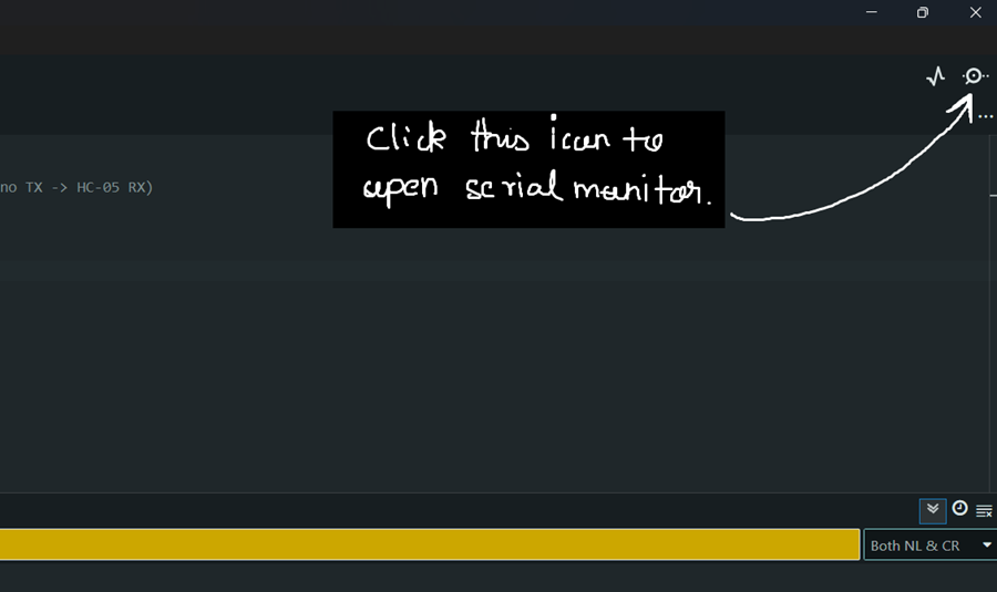
Now,
- Click on the button
- Check the serial output tab
- You should see "Button Pressed" printed!
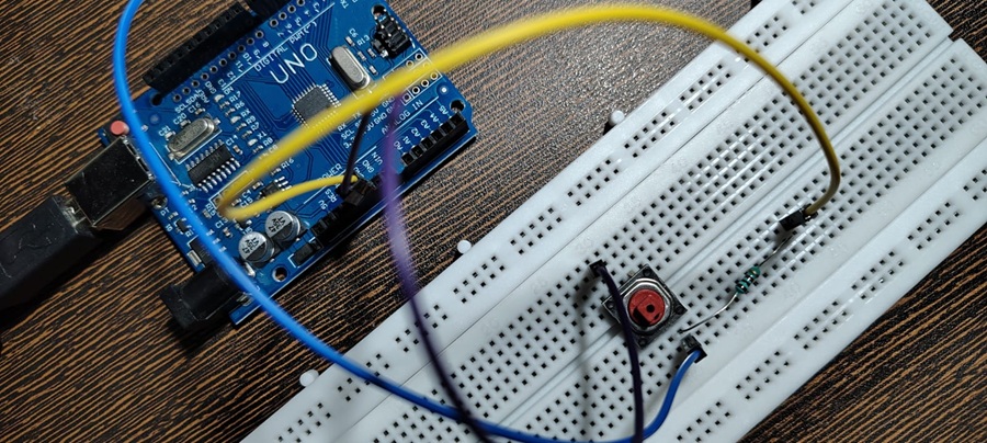
External Pull-Down Resistor Switch Circuit Demo
Code Explanation
const int buttonPin = 2;
A variable namedbuttonPinis created and assigned the value 2.
A variable is a named container that holds a value.
Instead of directly using pin numbers everywhere,
we use variables—this makes the code easier to modify and maintain later.pinMode(buttonPin, INPUT);
This sets pin 2 as an input pin, meaning Arduino will read voltage levels from it instead of sending voltage out.Serial.begin(9600);
This initializes the Serial Monitor and sets the communication speed to 9600 baud. Without this line, nothing will appear in the Serial Monitor.int buttonState = digitalRead(buttonPin);The variablebuttonStatestores the value returned by thedigitalRead()function.
digitalRead([pin name])
is an Arduino function that reads the state of a pin and returns:
- HIGH (1) → 5V
- LOW (0) → 0V
if (buttonState == HIGH) {code};
This is a conditional statement.
The code inside {} runs only if the given condition is TRUE (i.e., equals HIGH or 1).Serial.println("Button Pressed")
This prints the text inside the quotation marks to the Serial Monitor.else {Serial.println("Button Not Pressed");}
The else block runs when the if condition is FALSE.
In this case, it prints "Button Not Pressed".delay
This pauses the program for the given number of milliseconds.
The delay is added to make the Serial Monitor output easier to read.
When you press the switch, the voltage at pin 2 becomes 5V, causing the condition to evaluate as TRUE, and "Button Pressed" gets printed.
When the switch is not pressed, the pin stays at 0V, so "Button Not Pressed" is printed.
This process keeps repeating inside the loop() function.
Using the Internal Pull-Up Resistor
Now its the time to use the power of Arduino's Internal Pull-Up Resistor.
Arduino Pin 2 → Button → GND
That’s it.
No external resistor required.
In this configuration:
When the button is not pressed, the resistor pulls up the pin to 5v,
so Arduino reads HIGHWhen the button is pressed, the pin connects to GND,
and Arduino reads LOW
Once everything is connected properly, plug in your Arduino and upload the code below:
const int buttonPin = 2;   // Button connected to pin 2

void setup() {
  pinMode(2, INPUT_PULLUP);
  Serial.begin(9600);
}

void loop() {
  int buttonState = digitalRead(2);

  if (buttonState == LOW) {    // As you see we inverted the logic here!
    Serial.println("Button Pressed");
  } else {
    Serial.println("Button Released");
  }

  delay(200);
}
Hit Upload!
Use the Serial Monitor to see the output.
Now,
- Click on the button
- Check the serial output tab
- You should see "Button Pressed" printed!
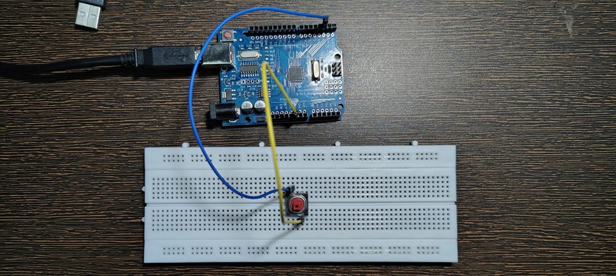
Internal Pull-Up Resistor Switch Circuit Demo
What Changed ?
pinMode(buttonPin, INPUT_PULLUP);
This sets pin 2 as an input pin connected to the internal pullup resistor.if (buttonState == LOW) {code};
As you observer we inverted the logic! When the voltage reads LOW, we know the button is pressed.
When you press the switch, the voltage at pin 2 becomes GND, causing the condition to evaluate as LOW, and "Button Pressed" gets printed.
When the switch is not pressed, the pin stays at 5V, so "Button Not Pressed" is printed.
🧰 Common Beginner Mistakes
Forgetting pull-up or pull-down resistors
Expecting stable readings from floating pins
Thinking button logic is “reversed by mistake”
Debugging code instead of checking wiring
Buttons fail electrically before they fail logically.
In short, the inputs are not information, rather they are change in the voltage at pins which gets interpreted as logic and we build our program around it!
Every sensor you come across will reduce its input information to a voltage level!
📌 What Comes Next
You may have noticed something odd:
- one button press sometimes prints multiple times
That’s not your fault.
That’s physics.
👉 Next Chapter — Debouncing: Why Buttons Misbehave
Coming SOON!