The Most Basic Definition
A switch is a device that intentionally opens or closes an electrical path.
In simple words:
By controlling when and how current flows, even a very simple device can control a circuit.
Let’s look at the most commonly used switches.
🔹 1) Push Button (Momentary)
A push button opens or closes a circuit only for the duration it is pressed.
Once you release it, the switch returns to its original state.
There is no state holding.
Types of Push Buttons
a) NO — Normally Open
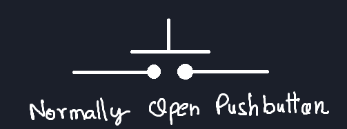
Circuit is open by default
Circuit is completed only while the button is pressed
b) NC — Normally Closed
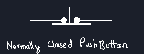
Circuit is closed by default
Circuit opens only while the button is pressed
Inside a Push Button (Super Simplified😅)
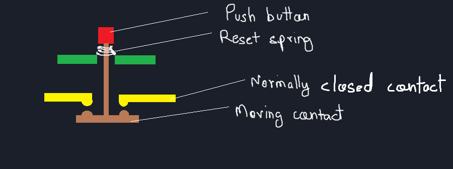
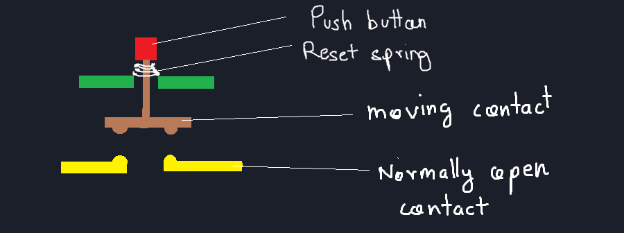
Inside a push button:
A small metal contact bridges/separates two terminals when pressed
When released, the contact separates/connects again
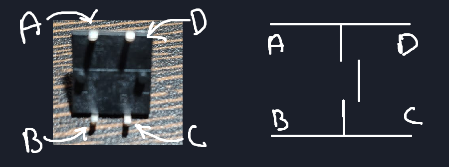
In common 4-pin push buttons:
The two pins on each side are internally connected
Pressing the button connects both sides together
💡 Simple trick:
This avoids confusion and wiring mistakes.
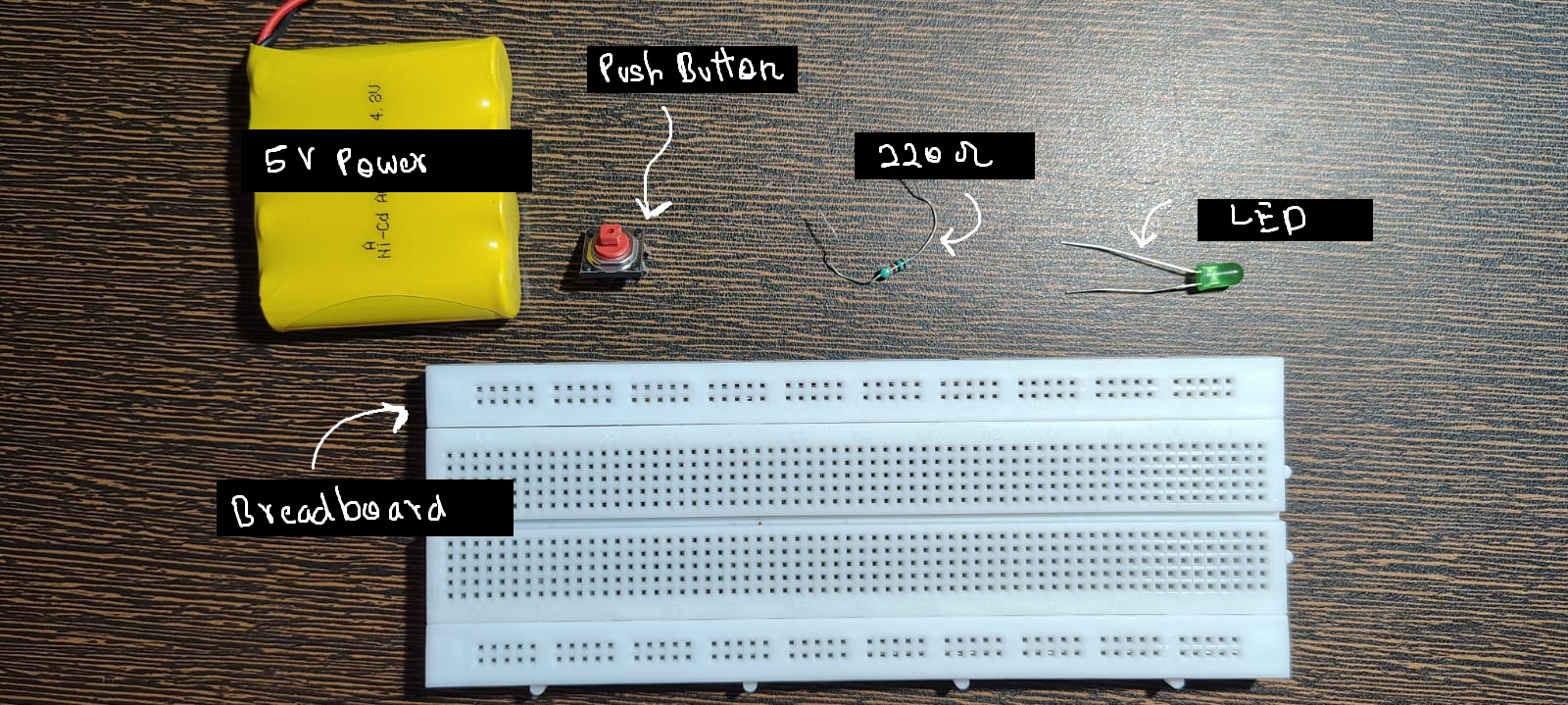
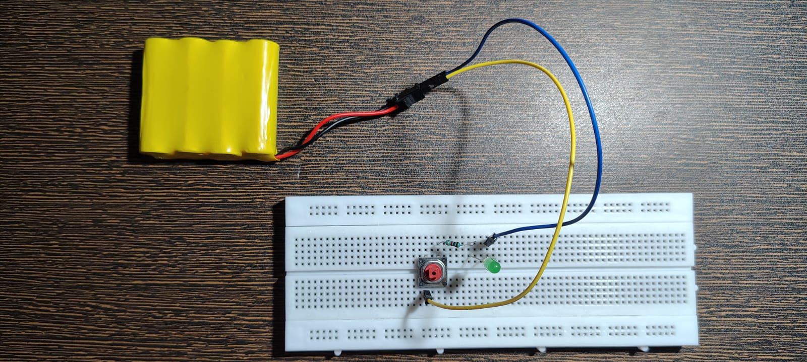
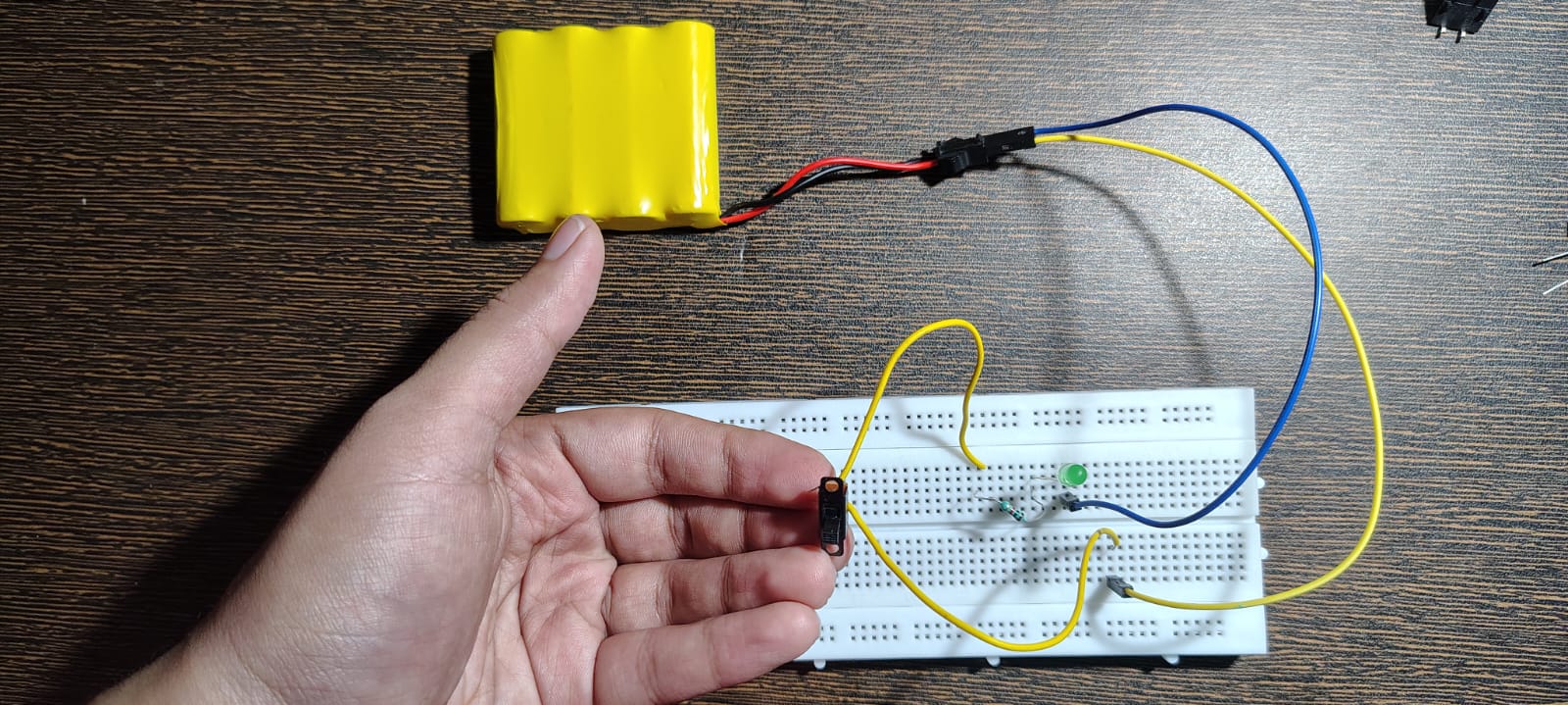
Practical Circuit — Push Button + LED
Component List:
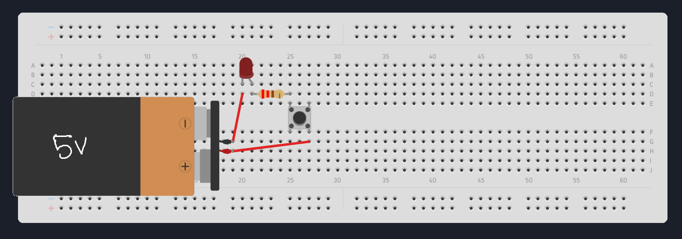
Circuit Diagram:
Completed Circuit:
Video Link:
Push Button Switch Test Demo
This lets you see current flow only while the button is pressed.
Where Push Buttons Are Used
Keyboard keys
Game controllers
Reset buttons
Momentary user inputs
Anywhere you want a temporary action, not a maintained state.
🔹 2) Toggle Switch
After momentary switches, we need switches that can hold their state even after the user lets go.
This is where toggle switches come in.
A toggle switch uses a mechanical latching mechanism that stays in position until changed again
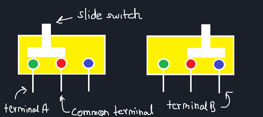
Inside a Toggle Switch (Super Simplified😅)
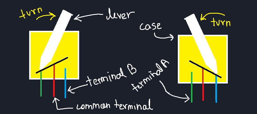
Internally:
A moving metal contact switches between two different plates
Each position completes a different circuit
This allows:
Circuit A in one position
Circuit B in the other position
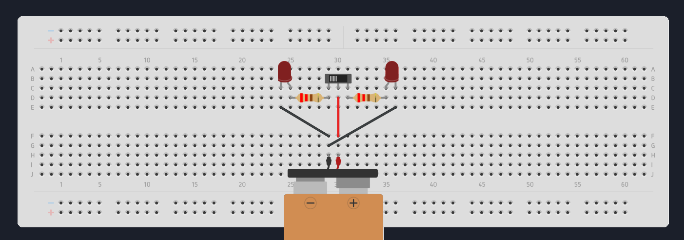
Practical Circuit — Toggle Switch + LED
Component List:
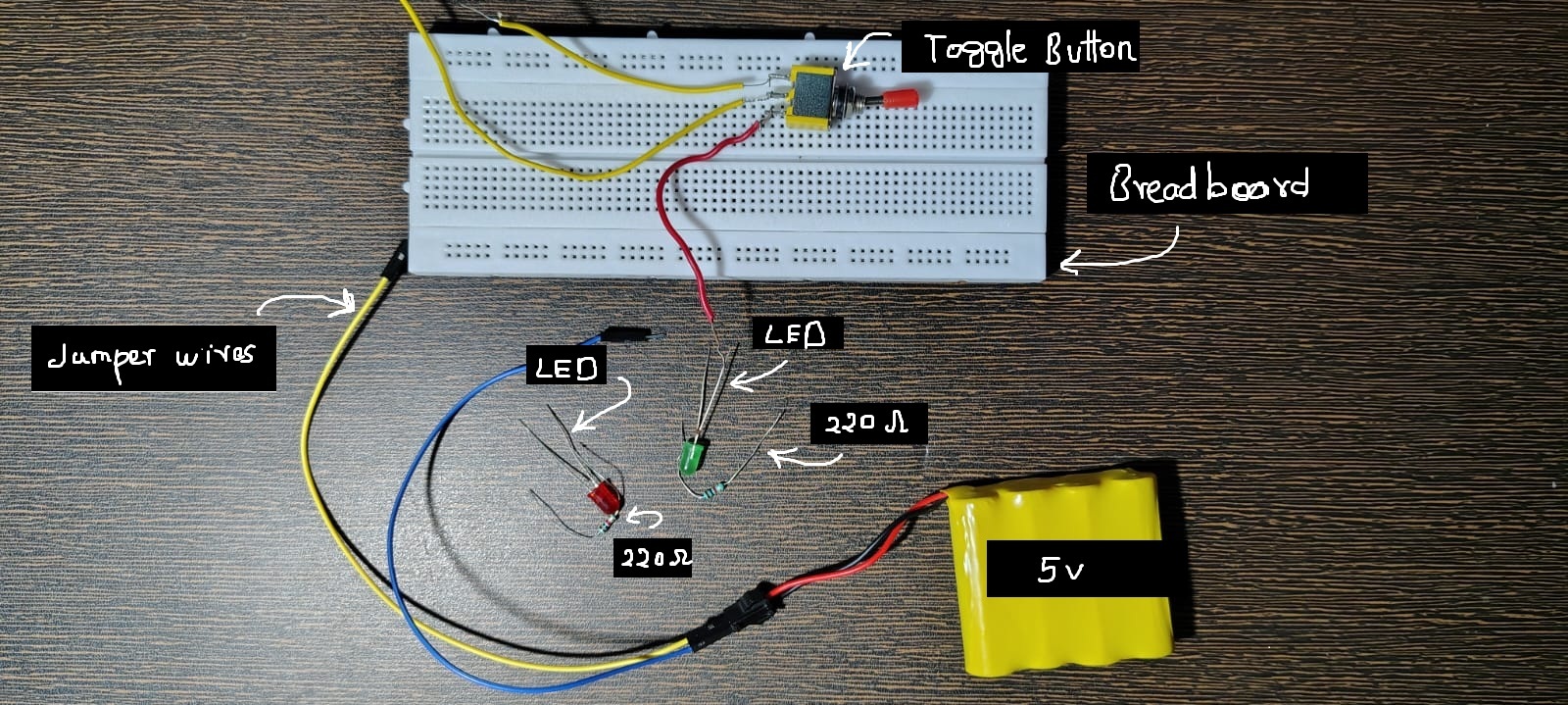
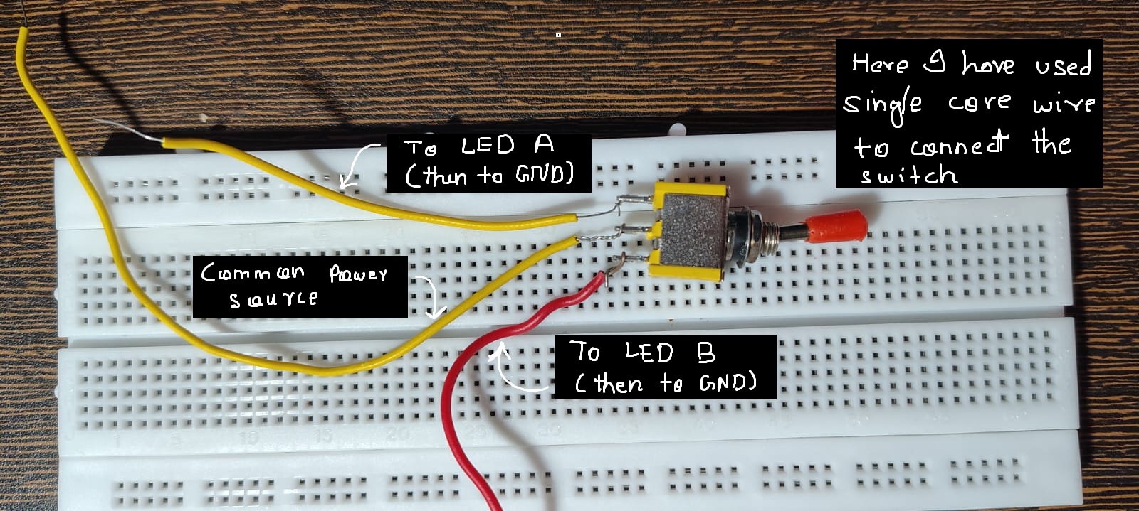
Circuit Diagram:
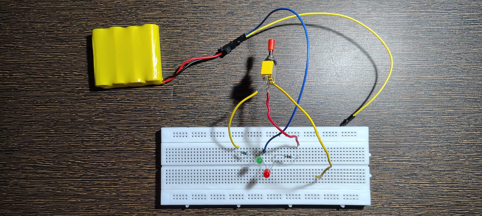
Completed Circuit:
Video Link:
Toggle Switch Test Demo
Making a Simple ON–OFF Circuit
If we remove the second circuit:
One position → ON
Other position → OFF
That’s how a basic ON–OFF switch works.
🔹 3) Slide Switch
Slide switches work on the same principle as toggle switches, but:
They are more compact
More stable for small boards
Commonly used on modules and PCBs
Why Slide Switches Are Sometimes Better
With toggle switches:
During switching, both contacts may briefly connect
This can momentarily short circuits or cause disturbances
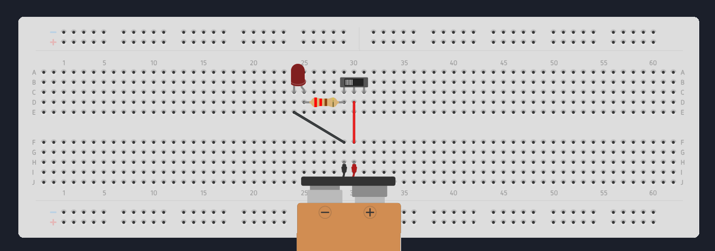
Practical Circuit — Slide Switch + LED
Component List:
Use the same components as toggle switch,
just replace the toggle swtich with slide switch. And
we need only
- 1 LED
- and 1 resistor
Circuit Diagram:
Completed Circuit:
Video Link:
Slide Switch Test
Quick Fact
Most ON–OFF switches you see on appliances are rocker switches
They are just another mechanical implementation of the same idea.
🧠 A Very Important Insight
Inside:
Metal contacts move
They hit
They bounce
They vibrate
⚠️ Switch Bouncing (The Hidden Problem)
When pressed:
Contacts bounce rapidly
This creates multiple ON–OFF transitions in a very short time
In analog circuits, this is usually ignored.
But in digital systems, especially with fast microcontrollers:
- One press can be read as multiple presses
We’ll handle this properly in an upcoming post on debouncing strategies. (On Jan 5!)
🔗 Switches + Microcontrollers
Now that you understand what a switch physically does,
we can let a microcontroller read that behavior.
I’ll link a dedicated article on digital inputs using a button here,
where we handle the code side properly.
❌ Common Mistakes (Short but Real)
Misunderstanding 4-pin push buttons
Floating connections
Loose jumper wires
Wrong pin pairing
Expecting perfectly clean ON/OFF signals
Golden rule:
the problem is mechanical, not logical.