Chapter 8
Until now, Arduino has lived in a binary world.
HIGH or LOW
ON or OFF
Pressed or Released
But the real world is not binary.
Light intensity, temperature, distance, pressure — these things change gradually.
To sense them, Arduino needs to move beyond digital logic.
That’s where analog input comes in.
🌊 What Is an Analog Signal?
An analog signal is a signal that can take many values, not just two.
Examples:
brightness of light
temperature of a room
position of a knob
sound amplitude
Instead of asking:
Arduino now asks:
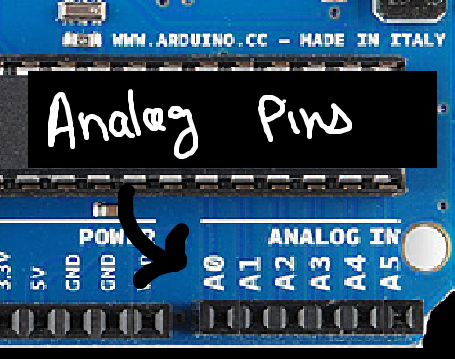
🔌 Analog Pins on Arduino
On the Arduino Uno, analog input pins are labeled:
A0, A1, A2, A3, A4, A5
These pins are connected to an internal circuit called the ADC
(Analog-to-Digital Converter).
🧠 What the ADC Actually Does
The ADC:
measures the voltage on an analog pin
converts it into a number Arduino can understand
On Arduino Uno:
input range: 0V to 5V
resolution: 10-bit
That means:
5V → 1023
Every voltage in between maps to a value between 0 and 1023.
🔢 analogRead() Basics
To read an analog value we use:
int sensorValue = analogRead(A0);
This returns a number between 0 and 1023,
depending on the voltage present at pin A0.
Similarly, we can obtain inputs from other analog pins!
🧪 Hardware Time: Reading a Potentiometer
Components Required:
- Breadboard
- Male to Female Jumper Wires
- Arduino UNO
- 10k Potentiometer
A potentiometer is the easiest analog sensor to understand.
It is a variable voltage divider.
Check this article to learn more about potentiometer.
Now,
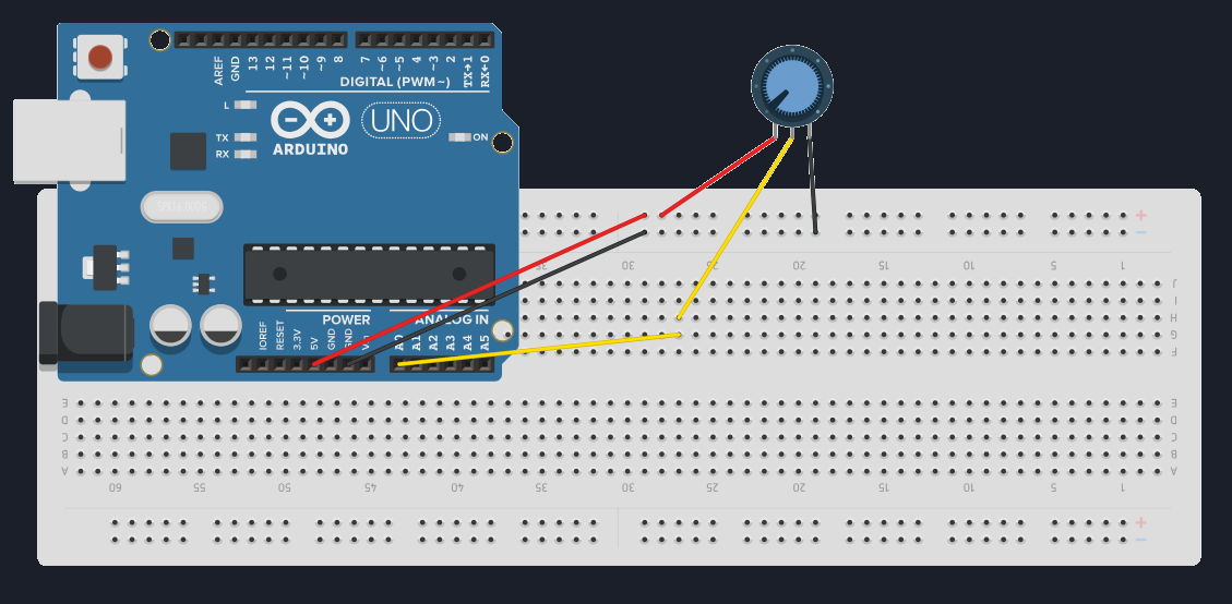
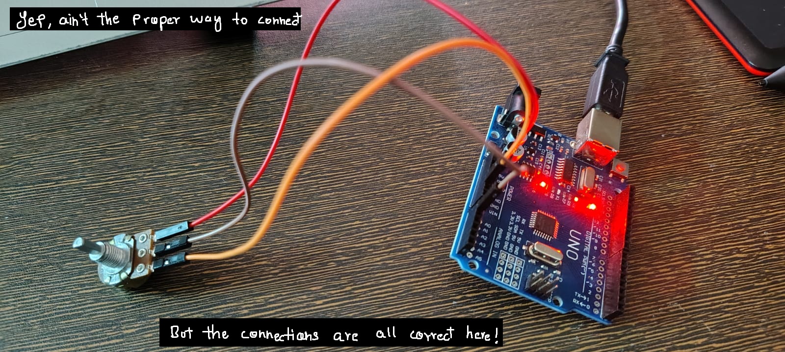
Connect the three pins of the potentiometer in the given way!
One end → 5V
Other end → GND
Middle pin → A0
Once done, upload the code given below to Arduino.
Code:
void setup() {
  Serial.begin(9600);
}

void loop() {
  int value = analogRead(A0);
  Serial.println(value);
  delay(200);
}
Paste and hit Upload!
Open the serial monitor on the top right corner.
Turn the knob and watch the numbers change.
Why didn't we use pinMode() here?
pinMode().
That’s because analog pins are input-only by default.
When you use analogRead(), Arduino automatically routes that pin to the internal ADC (Analog-to-Digital Converter).
In simple terms:
- digital pins need direction to be specified
- analog pins are already meant for reading voltages
🧠 What You Should Notice
The values change smoothly
Small turns → small number changes
Big turns → big number changes
This is fundamentally different from digital input.
⚠️ Important Things to Remember
Analog pins do not output voltage (by default)
They only measure voltage
Input voltage must stay between 0–5V
Exceeding this can damage the ADC
This why we require a voltage divider!!
🧰 Common Beginner Mistakes
Connecting sensors directly without a voltage divider
Expecting analog pins to “output analog voltage”
Forgetting to connect GND
Confusing analogRead() with PWM
These are normal mistakes. You’re learning how the real world behaves.
📌 What Comes Next
Now that we can read levels, the next step is to use those levels meaningfully.
👉 Next Chapter — Using Potentiometers & Mapping Values
This is where raw numbers become control.
Next Post Coming Soon!!