Chapter 2
Before you write a single line of code or connect a sensor, you must understand the board you’re working with. The Arduino Uno may look simple, but every pin and every component on it has a purpose.
Think of this chapter as a map of your territory — once you know the landscape, building circuits becomes 10× easier.
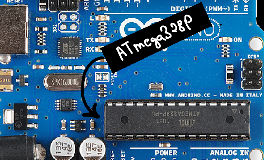
🔵 The Brain: ATmega328P
At the heart of the Arduino Uno is the ATmega328P, an 8-bit microcontroller that handles all your code and controls all pins.
It contains:
32 KB Flash memory → stores your program
2 KB SRAM → stores variables while the program runs
1 KB EEPROM → stores data permanently
Clock (16 MHz crystal) → acts like the board’s heartbeat
This tiny chip is why Arduino can read sensors, blink LEDs, run motors, and execute logic.
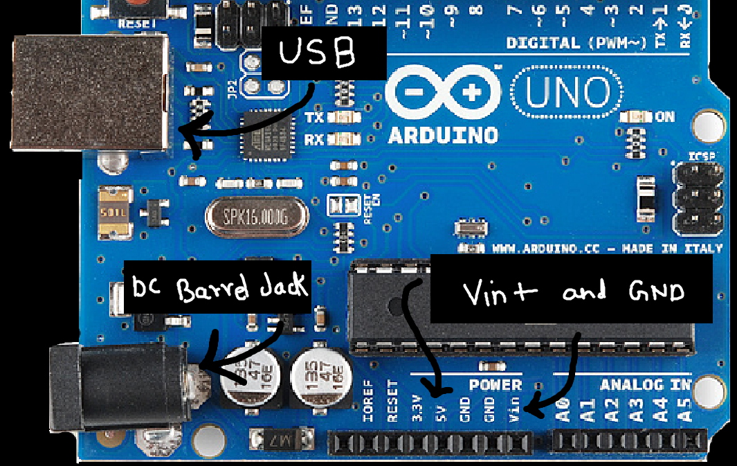
🔌 Power Section
The Uno can be powered in three ways:
USB (5V) – for coding and powering small circuits
DC Barrel Jack (7–12V)
VIN Pin (7–12V)
And it provides these regulated outputs:
5V pin → the main power rail for most modules
3.3V pin → for low-voltage sensors
GND pins → always connect ground when wiring
The power section also contains regulators that keep your board safe from voltage fluctuations. But still its a good practice to check your connections before powering the circuit!
🟩 Digital Pins (0–13)
These pins can:
Read HIGH/LOW
Write HIGH/LOW
Control digital devices (LEDs, buzzers, relays)
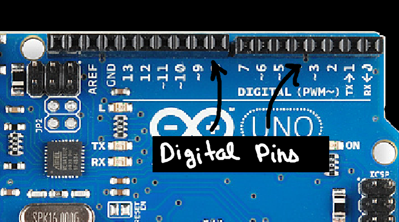
Special notes:
Pins 0 & 1 → connected to USB serial (avoid using them in projects)
Pins 2 & 3 → support external interrupts
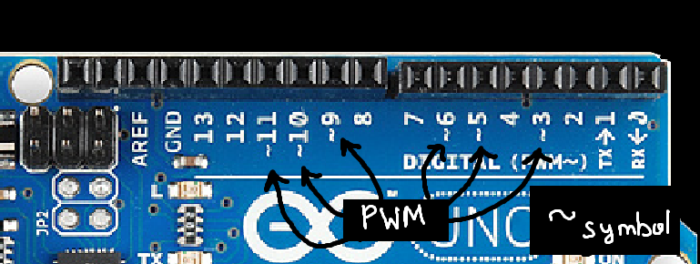
Pins 3, 5, 6, 9, 10, 11 → support PWM (~analog output)
PWM is used for:
LED brightness control
Motor speed control
Servo timing
🟧 Analog Pins (A0–A5)
These pins read analog values using the built-in ADC (10-bit):
Input range: 0 to 1023 (maps to 0–5V by default)
Perfect for sensors like temperature, LDR, potentiometer
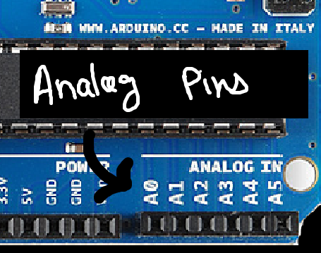
Some analog pins also support digital I/O if needed.
🔄 PWM Pins (3, 5, 6, 9, 10, 11)
PWM simulates an analog output using digital switching.
You’ll use PWM for:
Fading LEDs
Controlling motors
Generating signals
Building simple DAC-like outputs
You’ll explore PWM deeply later.
🧠 Communication Pins
1. Serial (UART)
Pins 0 (RX) and 1 (TX)
Used for USB communication and debugging.
2. I2C
A4 (SDA)
A5 (SCL)
Used for displays, IMUs, RTC, and multi-sensor setups.
3. SPI
Pin 10 (SS)
Pin 11 (MOSI)
Pin 12 (MISO)
Pin 13 (SCK)
Used for SD cards, wireless modules, high-speed sensors.
📍 Reset Button
Resets the microcontroller and restarts the program.
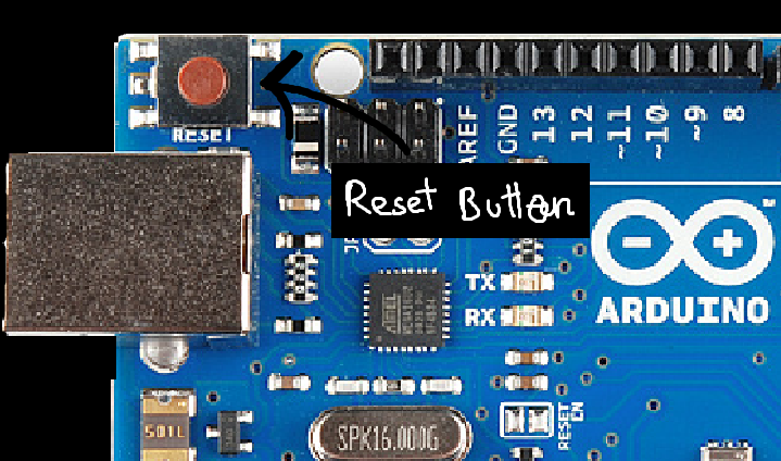
Useful when:
Code gets stuck
You need to re-run initialization
Uploading a sketch after a crash
💡 Why Understanding the Board Matters
When you know the board’s layout:
Wiring becomes intuitive
Errors reduce dramatically
Debugging becomes easier
Code feels more meaningful
You understand what’s actually happening on the hardware
This builds the foundation for everything you will do ahead.
",